Maglev Linear Motion Platform
An experimental magnetic levitation platform with analog control circuits, Hall-effect feedback and hardware designed in SOLIDWORKS. I'm building it with Prof. Kwee Yan Teh at SJTU.
1D vertical
STABILIZED AXES
Hall effect
FEEDBACK SENSOR
Analog + Arduino PWM
CONTROLLER
Overview
Magnetic levitation looks like magic, but it's really a control problem. An electromagnet pulling a permanent magnet upward is an unstable system. If the magnet gets too close it snaps to the coil, and if it drifts too far away it falls. To hold the gap you have to keep measuring the position and correct the coil current faster than the error grows.
I'm building that control loop from scratch as an Individual Project Pursuit (IPP) with Prof. Kwee Yan Teh at SJTU. There's no maglev kit and no off-the-shelf controller involved.
What I built
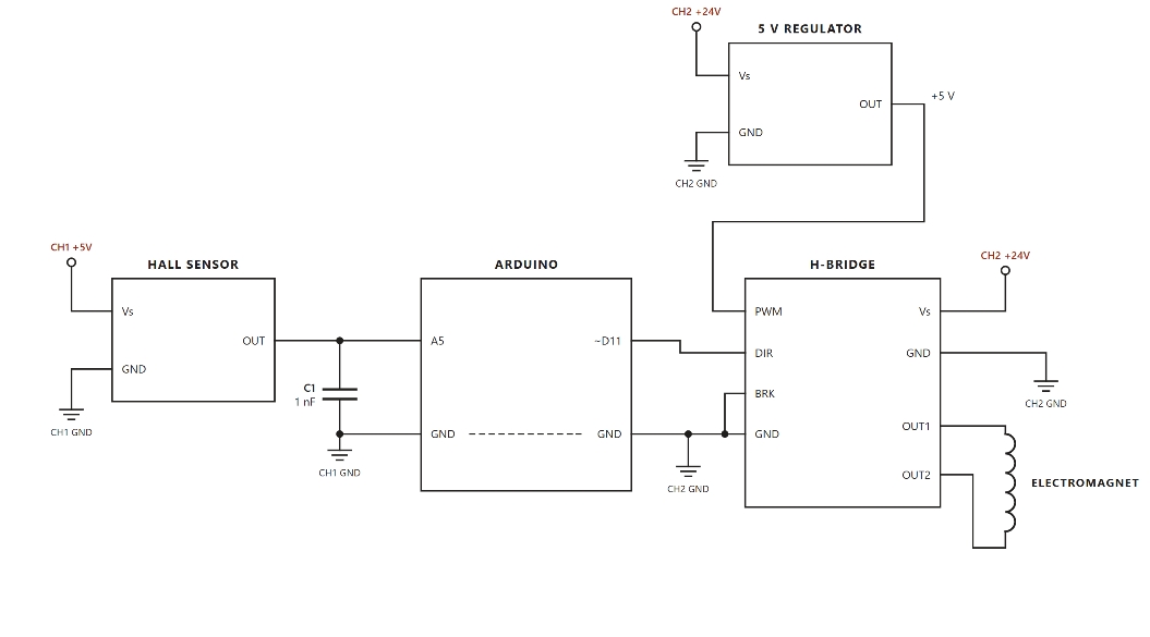
- Analog circuits for 1D stabilization. A Hall-effect sensor measures field strength, which tells you roughly how big the air gap is. That signal gets conditioned and used to drive PWM-controlled electromagnets with proportional control.
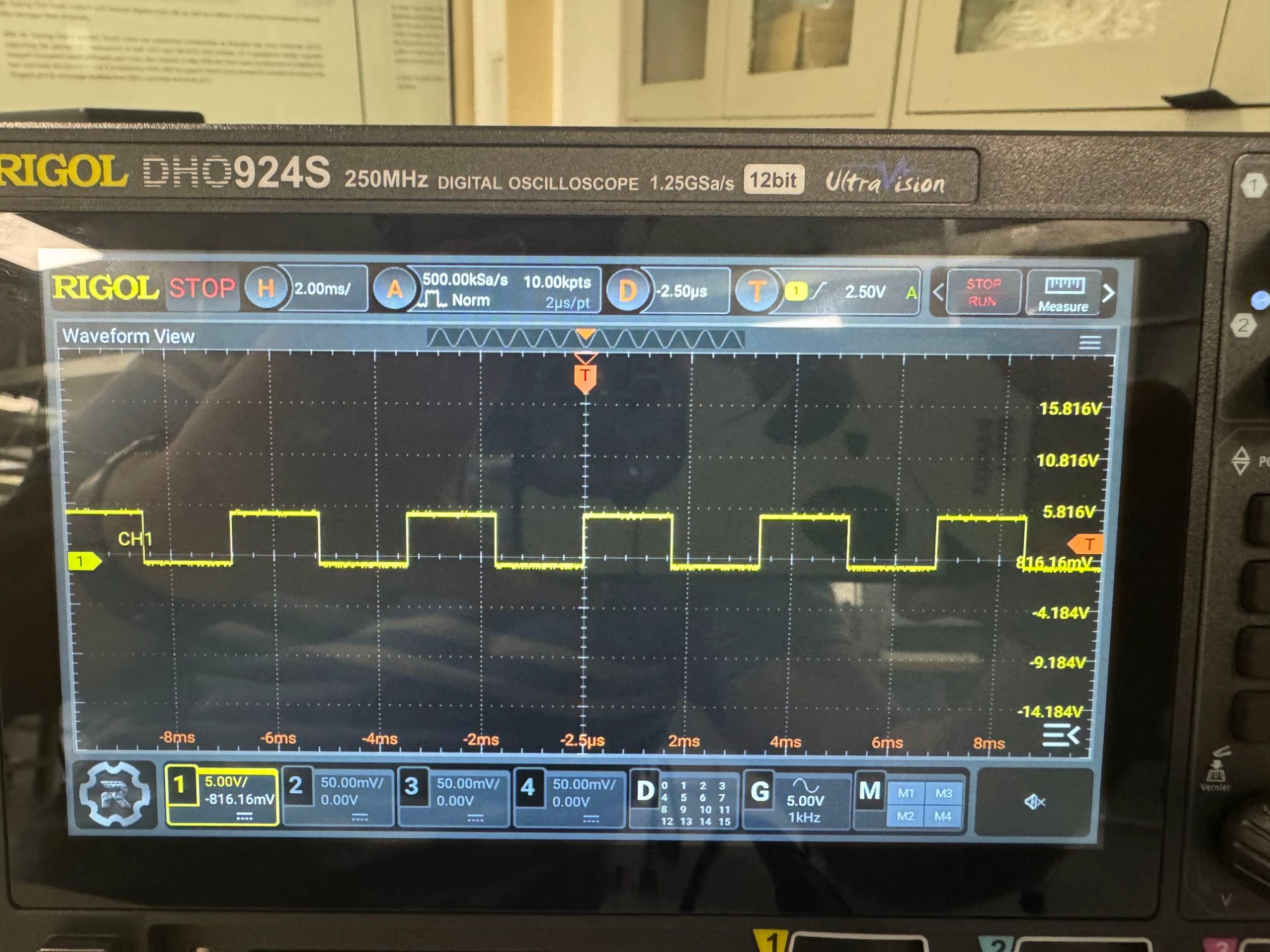
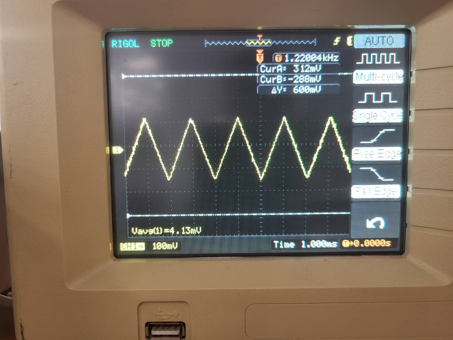
- An Arduino version of the MIC502 PWM controller chip. The original IC worked, but changing the tuning meant swapping resistors and capacitors. With the same behaviour in firmware I can change the loop parameters in code, which is a lot faster.
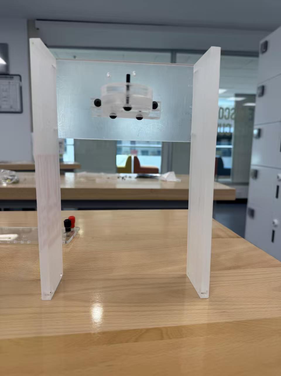
- Several electromagnet mounting platforms and supports in SOLIDWORKS. Most of the design changes were about keeping the solenoid axis vertical, because any misalignment shows up as sideways drift that a 1D controller can't correct.
Why I like this project
It needs electromagnetics, analog electronics, embedded code and mechanical design to all work together. If any one of them is off, the platform falls, so you find out very quickly when you've got something wrong.
Current state
The platform levitates stably in 1D with the Arduino controller. Next I want to measure how well the loop handles disturbances, and then work toward linear motion along a rail of coils.
APPENDIX A // MEDIA
VIDEO SLOT · AWAITING UPLOAD