Murphy's Tank: Automatic Gap-Crossing Vehicle
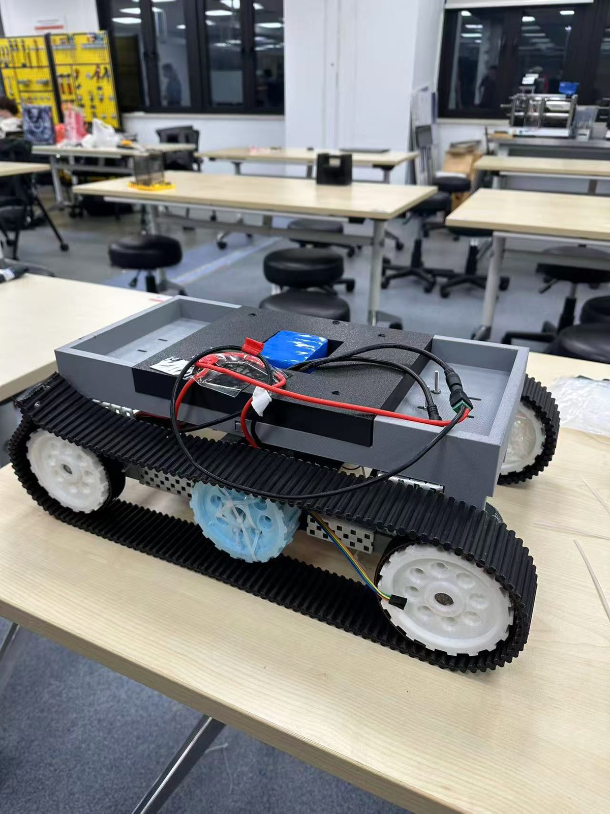
A tracked vehicle that drives itself across a 200 mm gap between two tables. Built by four of us for ME 2500J at SJTU, with a printed PLA frame, steel bracing, belt drive and an Arduino timer. It also carried a 75 kg person on flat ground.
200 mm
GAP CROSSED
~6 s
OFFICIAL RUN TIME
75 kg
PAYLOAD ON FLAT FLOOR
6.0 kg
VEHICLE MASS
RMB 399.60
FINAL PROTOTYPE COST
The task
The brief for ME 2500J was to build a vehicle that crosses a gap of at least 200 mm between two tables on its own. It had to start behind a line 200 mm before the gap, finish completely past a line 200 mm after it, move with no human contact once started, stay on the ground rather than jump or fly, and fit inside a 500 by 300 by 300 mm envelope at the start and the finish. Four of us worked on it as Group 5 over the summer term.
We decided early that we cared more about load capacity and structural strength than about speed, so the vehicle we ended up with is heavy, slow and stubborn.
Four concepts, and the one we picked
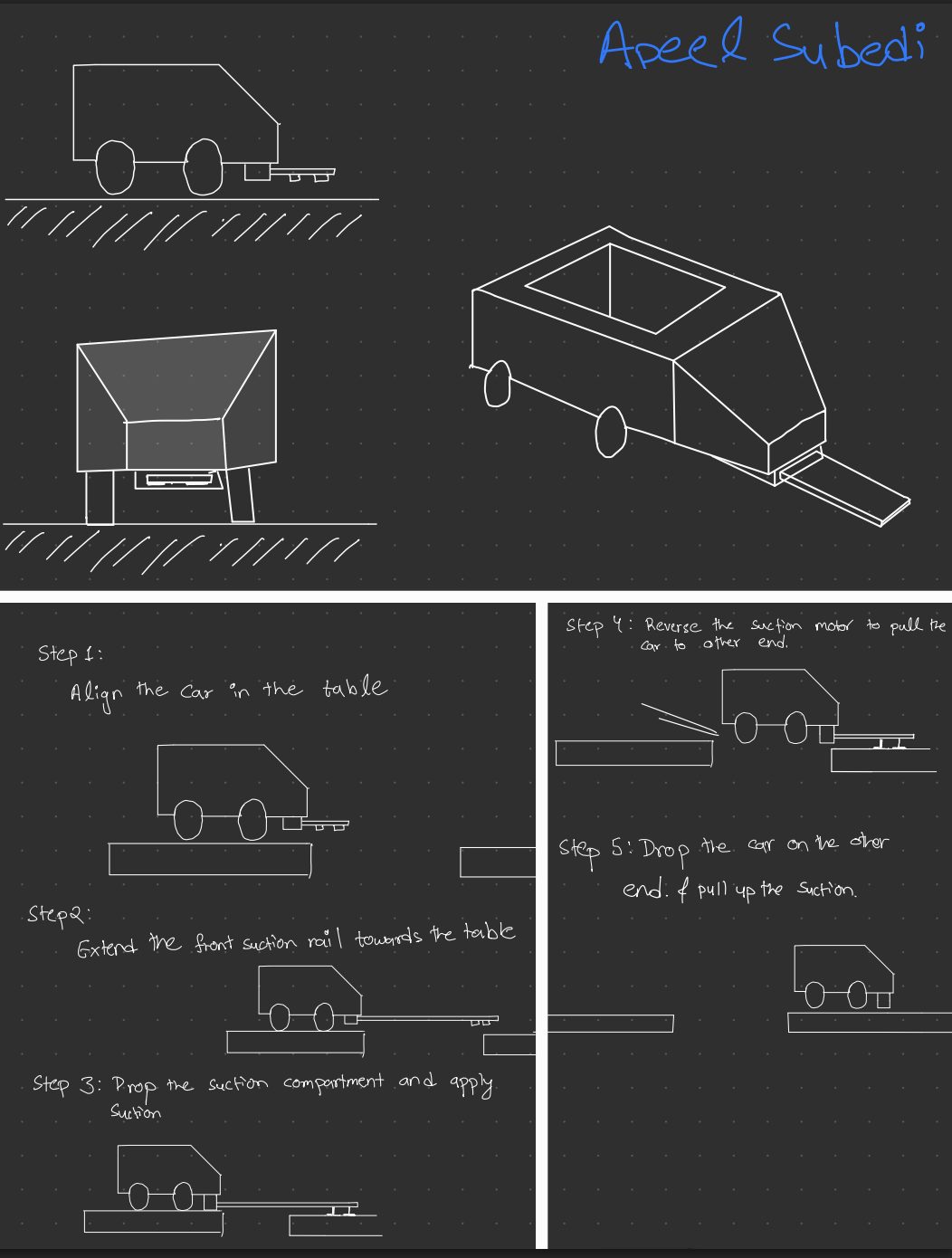
Each of us drew a concept. Mine was a suction-assisted transfer rail that would reach across to the far table and pull the vehicle over. The others were a long multi-wheel chassis, a rack-and-rail bridge that would extend rails from under the vehicle, and a tracked vehicle with continuous treads around six wheels.
We scored them on stability, payload capacity, manufacturing difficulty, mass and how reliably they would actually get across. The tracked concept won because it keeps a long contact region under the vehicle and needs only one motion to cross. The suction and bridge concepts both needed extra mechanisms and a multi-stage sequence, which is more to build and more to go wrong.
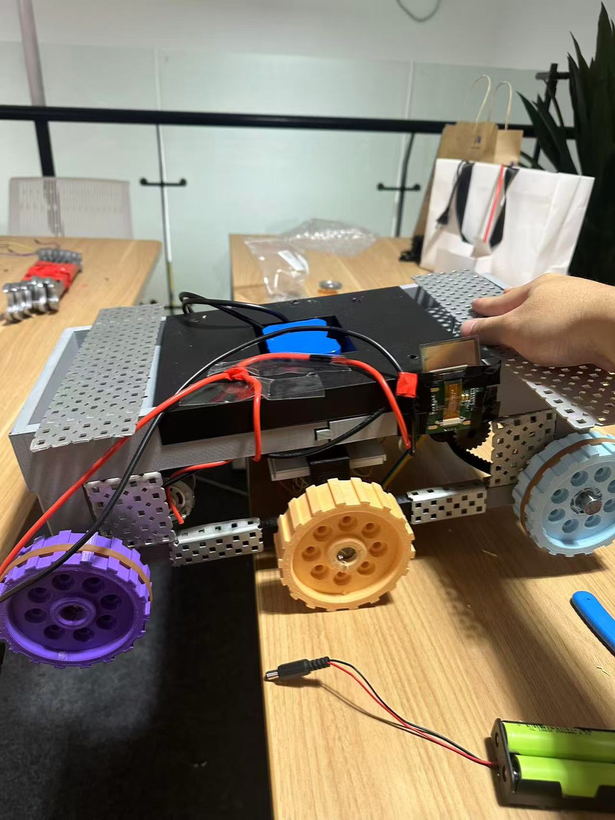
Then we made a decision that cost us a lot of time. For the first build we left the treads off to save mass and printing, expecting a long six-wheel chassis to reach across the gap by itself.
Why the six-wheel version kept tipping
It tipped every single time the front wheels reached the gap.
The numbers explain it. Our wheel spacing was 185 mm and the gap was 200 mm, so the gap was 15 mm wider than the spacing between two wheel pairs. When the middle wheels arrived at the near edge, the front wheels were still 15 mm short of the far table. There was no way to avoid a moment where the front wheels were supported by nothing.
At that instant the front reaction goes to zero and only the middle and rear wheels are left. Taking moments about the middle-wheel contact, the rear reaction works out as
N_R = -W e / s
where e is how far the centre of mass sits ahead of the middle-wheel contact.
If the centre of mass were exactly above the middle wheel, e would be zero,
the rear wheels would carry nothing, and the whole weight would sit on the
middle wheel pair. That is balanced, but only just: the vehicle is standing on
one line of contact. Move the centre of mass a few millimetres forward, which
the battery, the wiring and the motion itself all do, and e becomes positive.
The equation then asks for a negative rear reaction, and a table can only push
up, not pull down. Nothing can balance the moment, so the vehicle rotates
forward about the middle wheels and drops into the gap.
We did not work this out first. We suspected the free-spinning middle shaft, so we fixed it to the frame with adhesive and cable ties. It still tipped. We added small trolley wheels for extra contact points. It still tipped. We swapped the middle wheels for a wooden block, which sat at the wrong height and made things worse. Only after that did the geometry make it obvious that the problem was the gap in support, not the parts we kept changing.
What the treads fixed
Putting continuous treads around the three wheel stations means the vehicle touches both tables at the same time during the crossing. The two contact patches act like two separate reactions, one on the near table and one on the far table, with the centre of mass between them. Both stay positive, and the load hands over gradually from one table to the other as the vehicle advances. There is no single contact line for it to pivot about any more.
That is the whole reason the tracked version worked. The extra contact area matters much less than where the reactions sit relative to the centre of mass.
Frame: printed PLA with steel where it matters
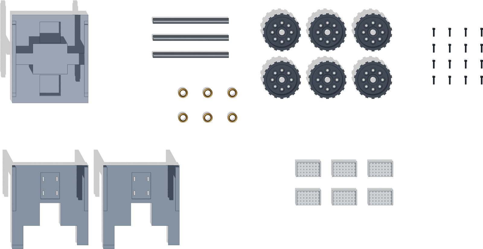
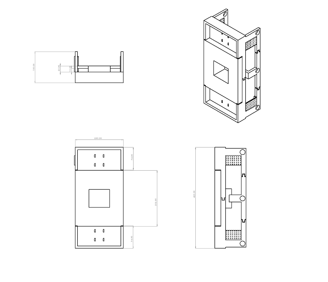
The chassis is three printed parts, a mid frame and two mirrored side frames, at 15% infill through the SJTU Student Innovation Center print service. Printing was the right call because the motor pockets, bearing bores, battery bay and electronics compartments are all internal features that we could build into the frame instead of bolting on brackets. It also let us reprint a frame for the cost of material when the internal layout changed, which it did several times.
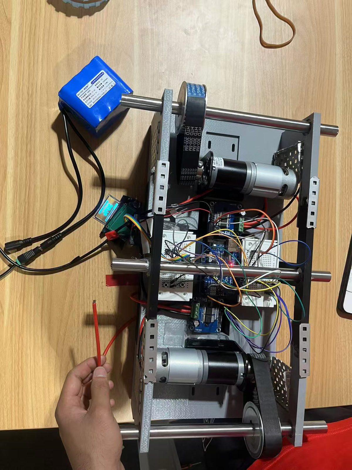
The battery sits in the centre of the mid frame, and the two motor driver compartments are mirrored about the centreline, so the electronics add no side-to-side imbalance. That matters because any yaw drift shows up exactly when the vehicle is halfway across the gap and can least afford it.
Six sheet steel braces go across the leg-to-body transitions of the side frames. Those corners see the highest bending moment when the vehicle overhangs the gap, and on a printed part they sit right on the layer bond plane, which is the weak direction. Bending each plate into a channel is what makes it useful: a flat strip has almost no stiffness about its weak axis, and turning the edges up raises the section stiffness enormously for the same weight of steel.
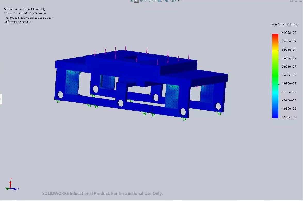
We checked the frame with a static analysis in SolidWorks at a 1000 N load, standing in for a 100 kg stretch goal:
| Result | Original frame | With steel braces |
|---|---|---|
| Max displacement | 0.09554 mm | 0.09767 mm |
| Max von Mises stress | 47.84 MPa | 49.89 MPa |
The reinforced model reports slightly worse numbers, which looks wrong until you remember the two versions were solved as separate assemblies with different meshes, extra bonded contacts and more steel mass. Peak values move around with mesh density. The plates were there to improve the load path around the axle holes and leg corners, not to lower a single global maximum.
Against the 51 MPa horizontal yield strength quoted for printed PLA, the simulated stress gives a factor of safety of about 1.02. That is close enough to 1 that keeping the steel was an easy decision.
Drivetrain and control
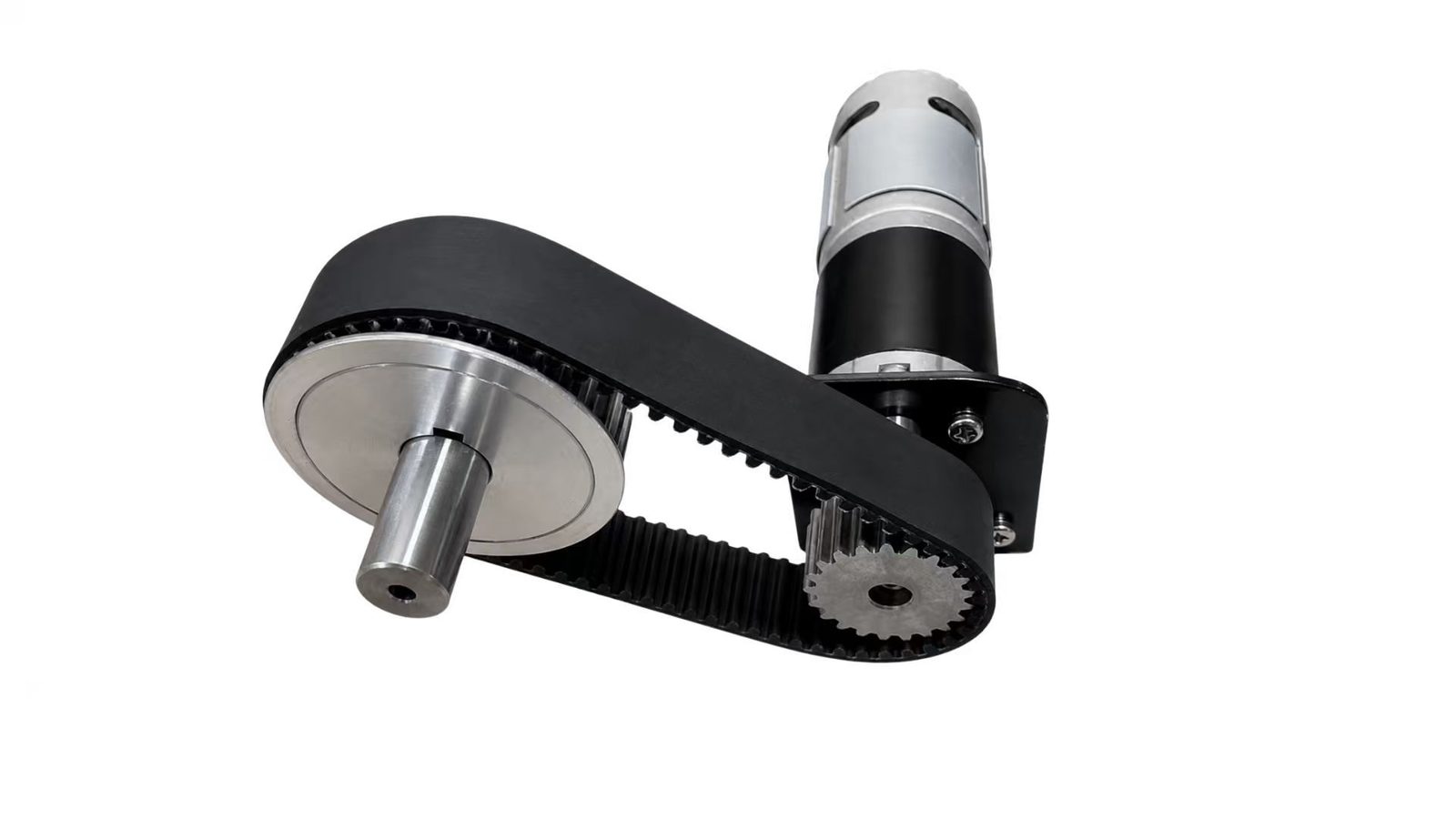
Two DC775 motors with 1:99.5 gearboxes drive the front and rear axles, rated at 60 rpm and 32 kgf·cm, which is 3.14 N·m each. HTD 300-5M timing belts give another 2:1 reduction, so each driven axle gets 6.28 N·m and the two together put 12.55 N·m at the wheels. Belts let us mount the heavy motors inboard, away from the axle line, and they absorb some of the shock when a wheel hits the far table edge instead of passing it into the gearbox.
With 50 mm wheels the datasheet numbers predict 0.0785 m/s. The successful run covered at least 1.12 m in about 6 s, which is 0.187 m/s, so the vehicle was more than twice as fast as the nominal calculation. The lesson is that the timing has to be calibrated from real runs, not from motor specs.
The controller is an Arduino Uno with three buttons and a small OLED display. Two BTS7960 drivers take the PWM. Power is split deliberately: a 12 V 10 Ah pack feeds only the motors, and a separate 7.4 V pack runs the Arduino and the logic side of the drivers. Sharing one pack would let the motor stall current drag the rail down far enough to reset the microcontroller mid-crossing, with the drivers still enabled.
The firmware is a two-state machine. While idle, the buttons set a speed percentage in 5% steps. Pressing start latches the run, records the time and drives forward until the 8 s window expires, then cuts the motors with the enable lines still high so they brake rather than coast. Each button is debounced over 30 ms, because a single bounce on start would otherwise restart the timer mid-run. It is open loop, so the percentage sets a duty cycle rather than a speed, and we trimmed it between trials.
Testing
On a flat floor the vehicle drove while carrying a person of about 75 kg. With the vehicle's own 6 kg that is roughly 795 N, and the PLA frame and steel legs showed no cracking or permanent bending. The minimum payload target for the project was 40 kg.
In the official gap-crossing trials it went one for two. In the successful run the front wheels cleared the 200 mm gap and the whole vehicle passed the finish line in about 6 s, against an 8 s target, and one tread had already started to come off by the end of it.
The finished vehicle measures 520 by 310 by 180 mm and weighs 6.0 kg. That is 4.0% over the preferred length and 3.3% over the preferred width, both inside the 5% band where deductions start. Parts for the final prototype came to RMB 399.60, and the whole project including abandoned parts came to RMB 769.60.
What I would change
The frame and the motors were never the problem. The treads were. We could not get correctly sized track material, so we cut surplus lengths and joined them with screws, which gave uneven tension and let the treads wander sideways off the wheels. The timing belts went on late and had no tensioners, so they loosened and slipped, which pulled the vehicle to one side and made the derailment worse.
Next time I would buy properly sized tracks, add lateral guides to keep them on the wheels, and put adjustable tensioners on both the belts and the treads. I would also finish the drivetrain much earlier, so there is time to test each stage of the crossing on its own instead of finding out during an official run.
APPENDIX A // MEDIA